
A heated hose for extruder lines rarely fails the way people expect. The melt is fine at the head and cold at the die, and the operator blames the hose. Usually the heater is doing its job. Heat is escaping through the fittings, the sensor is reading the wrong spot, or the end insulation is gone.
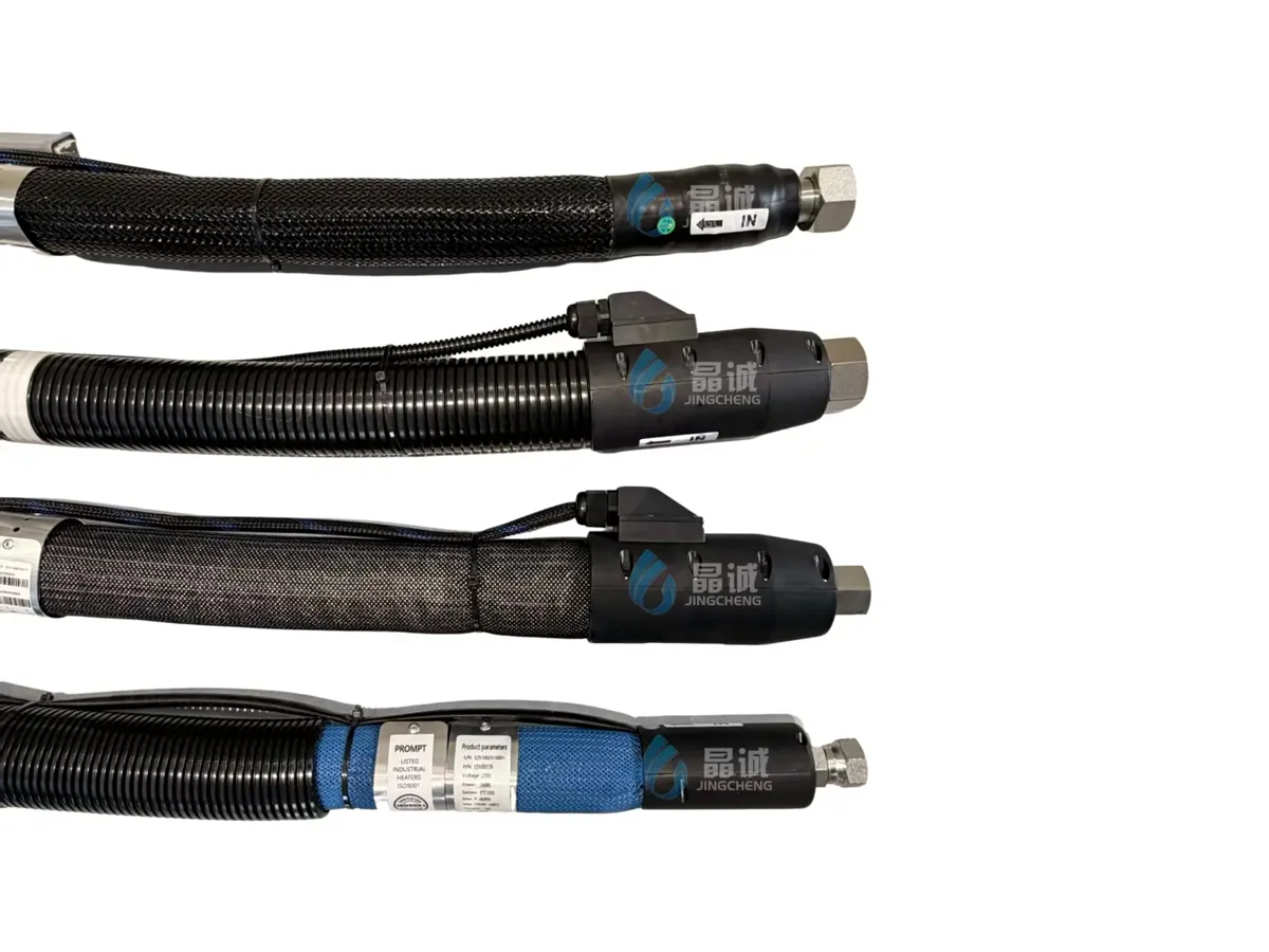
The call I get about every few months
A customer runs a small sheet line, a marking machine that lays thermoplastic through a die, or a compounding extruder feeding a strand head. Between extruder and die sits a heated hose, usually a few metres. Start-up goes fine. Twenty minutes in, the operator sees a dull band along one edge of the sheet, or an unmelted streak in the marking, or a die pressure gauge that climbs and then drops when screw speed is cut back. A probe on the last stretch before the die reads warm, not hot. The controller shows 250 °C (482 °F), and so does the setpoint.
So the hose gets swapped. The replacement behaves the same way within a week, and that is the detail worth stopping on: if a new hose reproduces the fault, the hose was not the variable. Something in the installation or control loop is taking heat out of the last part of the line. The hose is only where it shows.
What is actually happening at the die end
Four things cause most of it, usually in combination.
The heater stops where the fitting starts. A heated hose is hose, then end housing, then swivel nut, then the coupling on the die or the melt pump. The last two are unheated steel, and steel conducts heat out of the melt into the machine frame, so the stretch of flow path inside the unheated end runs cooler than everything upstream. That is ordinary heat transfer, not a defect, and every heated hose on the market shows the same shape of gradient. What differs is how much of the end is heated, how much steel sits between heater and melt, and whether anyone insulated the gap.
The sensor is measuring the wrong body. Most hose-end thermocouples sit in the end housing, a few millimetres from the melt channel but mechanically attached to a large steel part. If the controller holds that housing at 250 °C (482 °F), the heater runs hotter to do it, and the melt still loses heat across the unheated stretch after the sensor. The display is honest and the reading is still not melt temperature. The quieter version of the same fault is a sensor at the extruder end, where the melt arrives hot anyway, so the loop never sees the die end at all.
The heat is not evenly distributed. The heating layer in our hoses is a uniformly braided element, chosen to keep inner wall temperature even from end to end. Even distribution only works if heat loss is also even, and it is not. The ends lose more, and the cover opens at each end for the lead exit, where insulation gets compressed or torn during installation.
One control zone is doing two jobs. A common arrangement wires the hose and the die heater to one controller, or slaves the hose zone to the die. The die has more mass and more authority, so it wins the loop. The hose zone runs behind, the operator raises the setpoint to compensate, and the melt overheats at the extruder end while the die end stays cool.
How we trace it in an afternoon
You need a contact thermometer with a surface probe, a clamp meter, the drawing, and a run you can hold steady. What follows is general shop practice, not a figure from our catalog. Isolate the supply before touching wiring, and work only with people authorised on that line.
- Run to steady state first. Hold production setpoint and flow for at least half an hour with the die in place. A hose measured after a cold start tells you about warm-up, not the duty.
- Map the surface. Read at regular intervals from the extruder end to the die, then both end housings and the die adapter, and write the numbers in order. The shape of the curve is the diagnosis; the values only confirm the thermometer is sane.
- Check the controller against the map. Note what the display shows and what the probe reads at the sensor location. A gap of more than a few degrees means poor contact with the body the sensor is meant to represent, or a position where heat flow is not representative.
- Read the gradient, not the setpoint. A gentle, even fall along the whole length points to insulation loss or too little power per metre for the length and flow. A cliff in the last stretch before the die points to the fitting and the unheated end, and no extra setpoint will fix it.
- Check the heater circuit under load. With the controller output on, measure the supply voltage at the panel and again at the far end of the heater leads. A volt or two disappears in long runs and tired joints; the last section of the element then runs colder than the first, so a bad joint looks like a bad hose.
- Load-test it. Hold the setpoint and the screw speed for twenty minutes and log die pressure every two minutes. Pressure creeping up at constant speed means the melt is getting colder between the extruder and the die. Pressure steady but quality drifting points somewhere other than temperature, and you have saved yourself a hose.
The fix, cheapest first
Work down this list before ordering anything. On most lines the first two items are enough, and both are cheaper than a hose.
- Re-seat or move the sensor. Put the sensing point where it represents the melt, or accept that the end-housing reading is a housing temperature and say so on the drawing, so the die zone is trimmed against it deliberately rather than by guesswork.
- Insulate the exposed end. A removable jacket over the end housing and the first part of the coupling cuts the loss where it is worst. Keep it clear of anything that moves during a die change.
- Give the hose its own zone. A separate PID controller for the hose, with SSR or thyristor output, stops the die dominating the loop. On multi-hose lines, a multi-channel box keeps wiring and tuning in one place.
- Match power per metre to the length and the flow. A short hose with a large steel end and low melt flow needs more watts per metre than a long hose in still air, which is why the order form carries 110, 150, 170 and 200 W/m.
- Change the build. If the map still shows a cliff after the first four items, the end fittings or the inner tube are wrong for the duty, and that is the point where a new hose is the answer rather than a patch.
Where the extruder hose sits in our range
Our extruder connection hose is rated to 250 °C (482 °F) and up to 35 MPa (5,076 psi), the build we supply for extruders and line-marking machines. We have been a long-term supplier to domestic extruder makers, which is why the fitting end gets as much attention in the drawing as the hose body. Above 35 MPa the job moves to our special-industry connection hose: Daikin PTFE inner tube, 304 stainless pressure wire, 40 MPa (5,801 psi) and higher to order, but rated to 230 °C (446 °F). A high-pressure, high-temperature combination needs a conversation before a purchase order. Most of the rest of the range is rated to 230 °C (446 °F), with higher ratings on request.
| Item | Options | What it decides on an extruder line |
|---|---|---|
| Rated voltage | 380 Vac, 220 Vac, 110 Vac, 12 Vdc, other | Whether the hose runs from the machine panel or from its own controller |
| Temperature sensor | Type J, type K, Ni120, PT100, PT1000, other | Whether your existing controller can read it without a converter |
| Hose length | 3 m, 4.5 m, 5 m, 6 m, 10 m, other | Heat loss and pressure drop between extruder and die |
| Inner diameter | Φ8, Φ12, Φ16, Φ19, Φ25 mm, other | Flow rate at the pressure you need |
| Working pressure | 4 MPa (580 psi), 10 MPa (1,450 psi), 20 MPa (2,901 psi), 35 MPa (5,076 psi), other | Wall construction and end fitting |
| Rated power | 110, 150, 170, 200 W/m, other | How fast it recovers after a stop, and whether the end holds temperature |
| End fittings | US, British or metric threads, other | What it connects to on your die or adapter |
| Wiring | Pin table for the machine end and the die end | Which pin is heater, which is sensor, and which way the plug goes |
Build, wiring and control
Hose body, heater and electrical end are one assembly, and the model code keeps them tied together. Take the catalog example JCH-200-16-B-3X220-P2-8-N: 200 is the working temperature in °C, 16 a Φ16 mm bore, B a stainless-steel corrugated inner tube (TB is PTFE with a stainless braid, T plain PTFE, X a special material), 3X220 is three-phase four-wire 220 V, P2 a two-wire PT100 (P3 three-wire, K and J thermocouples, W no sensor), and 8 the working pressure in MPa. The trailing letter is not part of how we write a quotation, so confirm the full code on the drawing.
Two wiring details cause most callbacks. First, the pin table: every hose leaves with the pin number, wire colour and function for both ends, because a hose wired for the die end and plugged into the machine end will read nonsense or heat nothing. Second, the sensor type: a PT100 will not drive a controller set up for a type K thermocouple, and the mismatch reads as a wildly wrong temperature rather than a wiring fault.
The assembly is built for an ambient range of -40 °C (-40 °F) to +55 °C (131 °F), relative humidity up to 85 %, and 86 to 106 kPa, in air free of gases that corrode metal or attack insulation, free of conductive media and heavy mould. Extruder halls are usually fine on paper, sometimes not in practice: solvent vapour from a nearby printing station and spray from a cooling trough are both worth mentioning when you order, because a different environment is a custom build.
Symptom, likely cause, first check
| Symptom | Likely cause | First check |
|---|---|---|
| Dull band or unmelted streak at one edge | Cold end at the die, or uneven heat along the hose | Surface map of the last stretch of hose and the die adapter |
| Die pressure climbs at constant screw speed | Melt cooling before the die, narrowing the flow path | Pressure log against the temperature map |
| Controller reads setpoint but the product says otherwise | Sensor in the end housing or poor contact | Probe reading at the sensor location against the display |
| Last section of hose runs cooler than the first | Voltage drop in the lead run or a tired joint | Voltage at the panel against voltage at the far end, under load |
| Fault follows the hose when you swap it | Installation, control zone or fitting, not the hose | The whole line, before ordering a replacement |
Common mistakes we see on extruder lines
- Chasing the setpoint. Raising the hose setpoint to cure a cold die end overheats the melt upstream and can degrade it there. The die end stays cold because the loss is at the fitting, not the controller.
- Ordering by bore and length only. The fitting, the sensor type and the voltage decide whether the hose works on that line. A hose that fits but reads the wrong sensor is a return, not an installation.
- Hanging the hose off the fitting. The weight of a filled hose and its leads belongs on a support, not on the swivel nut at the die. A fitting under load leaks at the seat and reads cold at the same time.
- Cutting the outer cover to route the leads. The cover and the insulation under it are part of the thermal design. A slit at the bend is a permanent cold spot and an electrical risk.
- Replacing the hose before mapping the line. If the new hose behaves the same way, the money went into a spare rather than a fix. Half an hour with a contact thermometer usually finds the cause.
What to send for a quotation
Send the die or adapter drawing, the melt temperature and flow rate, the working pressure, the supply voltage, the controller input, and how the hose will be routed and supported. A temperature map from the diagnosis above tells us whether the new hose needs a heated end or a higher power density before we quote. The heated hose specification checklist lists the twelve inputs we need, and the hot melt hose page covers the adhesive-machine version of the same assembly if your line dispenses rather than extrudes. Quotations follow the same six steps every time: inquiry, specification confirmation, quotation, purchase order, production to the confirmed specification, then inspection, packing and shipment. Final ratings for each project are fixed on the quotation and drawing, not on this page.
Frequently asked questions
What temperature can an extruder heated hose hold?
Our extruder connection hose is rated to 250 °C (482 °F). Most of the rest of the heated hose range is rated to 230 °C (446 °F), and higher ratings are available on request. The number that matters is not the maximum but the die-end temperature under flow, which is why we ask for routing and flow rate.
What pressure can it take?
Up to 35 MPa (5,076 psi) in the standard extruder hose. Above that, the special-industry connection hose is built to order at 40 MPa (5,801 psi) and higher, with a Daikin PTFE inner tube and 304 stainless pressure wire, but it is rated to 230 °C (446 °F), so a high-pressure and high-temperature combination has to be checked case by case.
Can I run it from the machine's existing controller?
Usually yes, if the sensor type and the voltage match. The order form covers 12 Vdc to 380 Vac and type J, type K, Ni120, PT100 and PT1000 sensors. Where the hose needs its own zone, our PID controllers come with SSR or thyristor output, an optional waterproof enclosure and volt/ammeter, and multi-channel control boxes for lines with several hoses. See the heated high pressure hose range for the family this hose belongs to.
How do I know whether the hose or the machine is at fault?
Swap-test it or map it. If a known-good hose reproduces the cold end, the loss is in the fitting, the sensor position or the control zone. If the map shows a cliff only at the end housing, the hose is behaving normally and the end needs insulation or its own heat. The PTFE hose selection guide explains the inner-tube constructions if the question turns out to be chemical or flow related rather than thermal.
Send your extruder hose details
Tell us the melt, the temperature, the pressure, the bore and what the hose connects to at each end. We will come back with the specification we would build and the drawing to sign off.
Request an extruder hose quotationSoren Miles, Marketing Manager | JC
Mobile: +86 13087118553 / +1 (757) 733-8947
WhatsApp: +86 185 6950 4906
Email: soren.miles@shenzhenjingcheng.com
Company (Canada): JINCHEN ELECTRIC TRACING CO., LTD.
Company (Hong Kong, China): HK JINGCHENG HIGH TECH CO., Ltd
Company (China): SHENZHEN JINGCHENG HIGH TECH CO., Ltd / Jingcheng Fluoroplastic (Guangdong) Co., Ltd.
Website: https://www.jingchenghose.com | https://www.electricallyheatedhose.com
Factory address: No. 7 Qiguan East Road, Torch Development Zone, Zhongshan City (Jingcheng Industrial Park)
Sources: Jingcheng 2025 electrically heated hose catalog (extruder and special-industry connection hoses, order form, model code, operating conditions) and our published business policies. The diagnostic sequence and the heat-loss explanation are general engineering practice, not catalog data. Final ratings for each project are confirmed in the quotation and drawing.